

These days ready-to-use DC-DC converters are everywhere, with some of the cheaper ones even being safe to use without an immediate risk to life and limb(s). This piques one’s curiosity when browsing various online shopping platforms that are quite literally flooded with e.g. QS-4884CCCV-1800W clones of a DC-DC boost converter. Do they really manage 1800 Watt even without active cooling? Are they perhaps a good deal? These were some of the questions that [Josh] over at the [Signal Drift] channel set out to answer.
The only real ‘datasheet’ for this module seems to come courtesy of a Floridian company who also calls it the 36843-PS, but it features specifications that are repeated across store listings so it might as well by the official ‘datasheet’. This module is marketed as being designed for the charging of lead-acid and similar batteries, including the boosting of PV solar panel outputs, though you’d really want to use an MPPT charger for that.
With this use case in mind, it’s probably no surprise to see on the oscilloscope shots under load that it has a tragic 100 kHz switching frequency and a peak-to-peak noise on the output of somewhere between 1-7 VDC depending on the load. Clearly this output voltage was not meant for delicate electronics.
Looking closer at the board, we can see that it features a TI TL494C as the PWM controller IC, which drives the MOSFETs that form the boost circuit. There’s also an XLSemi XL7005A buck converter that is used for the low-voltage supply on the board. Meanwhile an LM358 dual opamp seems to be used in the voltage monitoring circuit, which also completes the analysis minus the passives, the MOSFETs for the buck (IRFB3206) and boost (IRFP4468) circuits, and a 100V-rated Power Schottky rectifier.
While the board does implement some basic voltage- and current-related safeties and limits, even the documentation tells you to not leave it powered on for too long. As for pushing it to the full 1,800 Watt output, this would require at least 48 VDC input, enabling e.g. 90 VDC output at 20A. Since the input terminal is only rated for 300V at 30A, the input for the subsequent stress test was limited to 48V at 30A for a total of 1,440 Watt from three 48 Watt PSUs.
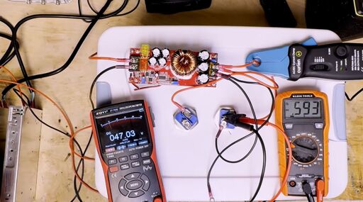
Using two resistive heating elements as a ~1,800 Watt load the output of the module was measured to see how far the module can be pushed. This turned out to be 1,200 Watt with the 48VDC input proving to be the limit. With the maximum 60VDC input you may be able to provide the current required to hit the full 1,800 Watt, but at that point you’re pretty close to the output voltage anyway. This makes a total of 500-1,000 Watt more reasonable.
Considering the overall performance, the original listed application as a battery charger seems to be about right, with a very barebones design. Its output switching noise and lack of safeties, as well as inability to fully turn off, mean that it should not be used by itself for anything that will be powered for extended periods of time, nor should anything sensitive to switching noise be exposed to its output voltage. For the $18 or so that this module goes for on certain popular platforms one could do much worse if you know what you’re doing.
From Blog – Hackaday via this RSS feed
You must log in or # to comment.