

A team of hackers, [Jason T. Jacques], [Decle], and [Michael A. Wessel], have collaborated to deliver the Microtronic Phoenix Computer System.
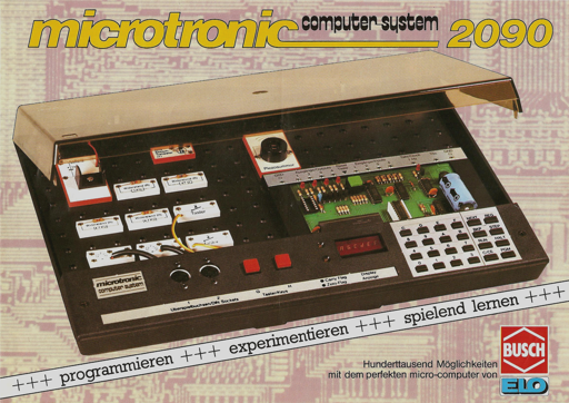
In 1981 the Busch 2090 Microtronic Computer System was released. It had a 4-bit Texas Instruments TMS1600 microcontroller, ran at 500 kHz, and had 576 bytes of RAM and 4,096 bytes of ROM. The Microtronic Phoenix computer system is a Microtronic emulator. It can run the original firmware from 1981.
Between them the team members developed the firmware ROM dumping technology, created a TMS1xxx disassembler and emulator, prototyped the hardware, developed an Arduino-based re-implementation of the Microtronic, designed the PCB, and integrated the software.
Unlike previous hardware emulators, the Phoenix emulator is the first emulator that is not only a re-implementation of the Microtronic, but actually runs the original TMS1600 firmware. This wasn’t possible until the team could successfully dump the original ROM, an activity that proved challenging, but they got there in the end! If you’re interested in the gory technical details those are here: Disassembling the Microtronic 2090, and here: Microtronic Firmware ROM Archaeology.
The Phoenix uses an ATmega 644P-20U clocked at 20 MHz, a 24LC256 EEPROM, and an 74LS244 line driver for I/O. It offers two Microtronic emulation modes: the Neo Mode, based on [Michael]’s Arduino-based re-implementations of the Microtronic in C; and the Phoenix Mode, based on [Jason]’s Microtronic running the original Microtronic ROM on his TMS1xxx emulator.
The Phoenix has a number of additional hardware features, including an on-board buzzer, additional push buttons, a speaker, 256 kBit 24LC256 EEPROM, and six digit 7-segment display. Of course you have to be running in Neo Mode to access the newer hardware.
There are a bunch of options when it comes to I/O, and the gerbers for the PCB are available, as are instructions for installing the firmware. When it comes to power there are four options for powering the Phoenix board: with a 9V block battery; with an external 9V to 15V DC power supply over the standard center-positive 2.5 mm power jack; over the VIN and GND rivet sockets; or over the AVR ISP header.
If you’re interested in the history we covered [Michael Wessel]’s Arduino implementation when it came out back in 2020.
From Blog – Hackaday via this RSS feed